This is an old revision of the document!
Table of Contents
Creating vis files from d4 personalities
(This is NOT an official documentation but simply based on my personal experiences - it might be not complete or even simply wrong in some aspects. Please give feeback if you find anything that you think should be improved.)
Even though the old visualiser is now superseded by Capture it might be useful for some - and as personalities for the visualiser are not made any more, here are some hints how you can make them from d4 Titan personalities.
A pre-requisite is of course an up-to-date manual or at least DMX chart of the fixture you want to do files for.
1. Check if there really doesn't exist one
Use the search on https://personalities.avolites.com/ to check if there really doesn't exist what you need - downloading is always faster than attempting to do yourself.
2. Update your personality library
You certainly do not want to work with old data. Thus, download and install the latest Titan Fixture Library from https://personalities.avolites.com/.
3. Prepare a skeleton folder structure
This process will produce a couple of files which all need to go to designated folders. It has proven to be useful to have such a folder structure while preparing vis personalities:
My Fixture
    // You may put the manual/DMX-Chart here //
    Avolites
        Titan
            FixtureLibrary
        Visualiser
            Personalities
            Extensions
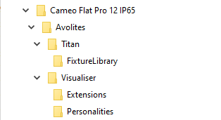
Example:
4. Identify the correct d4 file
We assume that a d4 personality for your fixture already exists. Luckily they usually have verbose file names - have a look in the personality folder (with the PC suite installed it is C:\Program Files (x86)\Avolites\Titan\FixtureLibrary). If you don't find what you need then search at https://personalities.avolites.com/ or https://www.avolites.de/downloads/d4find for the correct filename. If you still don't find anything then request the personality for Titan or build it yourself (this might be explained on another day).
If you have found the correct d4 file copy it to \Avolites\Titan\FixtureLibrary in the folder structure.
Now, our example looks like this:
CAMEO FLAT PRO 12 IP65
│   CLPFLATPRO12IP65_Cameo_Bedienungsanleitung_EN_DE_FR_ES.pdf
│   CLPFLATPRO12IP65_Cameo_DMX_Control_table.pdf
│
└───Avolites
    ├───Titan
    │   └───FixtureLibrary
    │           Cameo_FLAT PRO 12 IP65 (CLPFLATPRO12IP65).d4
    │
    └───Visualiser
        ├───Extensions
        └───Personalities
Then doubleclick the d4 file to open it in the Titan Personality Builder.
5. Create/check Pearl references
In the personality builder expand the modes section (left panel). One by one click on each mode and check that there is a setting in the Classic Pearl Reference field bottom right. This makes the reference from Titan to the visualiser.
If there is no entry then you need to make one yourself:
- albeit max. 11 characters yre allowed you make your life easier if you use max. 8 characters
- no spaces, no special characters, no umlauts, no symbols - just characters and numbers
- a good habit:
- start with two characters denoting the manufacturer (i.e. “RO” for Robe, “UK” for Unknown etc.)
- four to five characters for the fixture name
- one or two characters for the mode
- each reference must be distinct
Here it is already set as UKCMF125 which could be derived from
- UK as Unknown (this was where Cameo was listed previously)
- CM from Cameo
- F12 is a very brief abbreviation for
Flat Pro12 - 5 denotes mode 5
If you need (or want) to make your own entries then please check if a similar file (with an .R20 extension) already exists in C:\Program Files (x86)\Avolites\Visualiser\Personalities. If it does then use another reference. Again, each reference needs to be unique.
If you have changed anything then don't forget to save it with Save from the Files menu.
6. Generate R20 (and Vis) files
Now let's Personality Builder do its magic to prepare the files – it will most likely need our help for this though 
From the File menu select Generate R20 Files…
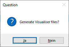
The next prompt asks if you want to create Visualiser files as well. Confirm this with Yes.
Now, one by one, Personality Builder scans each mode. For each mode, two files are created: an .R20 file (like he classic pearl files) and a vis file which is the actual visualiser personality. However, things usually don't go that smoothly.
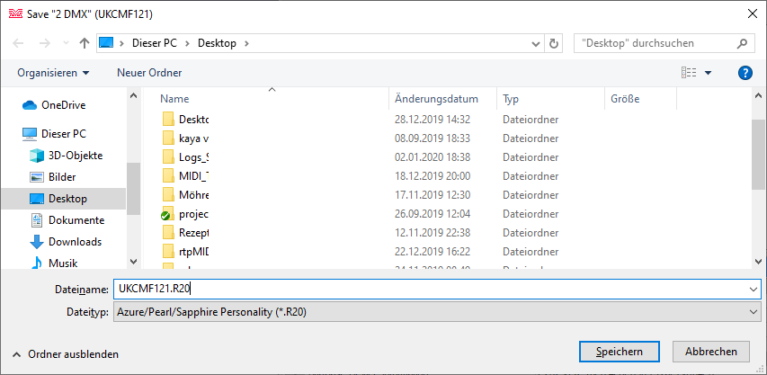
The next prompt asks where the file should be saved - usually we can just confirm this (the filenam is created from our unique reference…):
Next, depending from the d4 file some prompts may be shown, e.g.
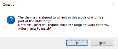
The channels assigned to wheels in this mode only utilise
part of the DMX range.
Note: Visualiser will require complete range to work correctly.
Adjust limits to match?
Usually I select No here as we will check and correct the vis file manually anyway.
Another such prompt:
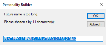
Fixture name is too long.
Please shorten it by 11 character(s):
.....
Here, you need to comply - shorten the given fixture name as only 31 characters can be displayed in the visualiser. This needs to be done per mode - it's a good idea to use something like 'm1', 'm2' or such to distinguish the modes. Here, I set the given name to FLAT PRO 12 m1.
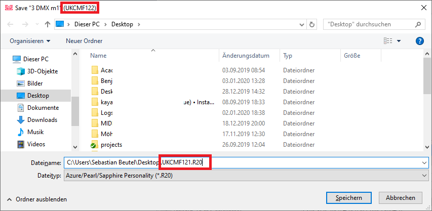
Now the next mode is parsed and checked. Again we get the prompt asking for the filename. This time it really needs to be checked and corrected as it again suggests the name derived from mode 1. Change the filename for the one which refers to the reference of mode 2 (as suggested in the prompt's title bar):
Here it again suggests the filename UKCMF121.R20 - however, the title bar tells that we have to change this to UKCMF122.R20.
Proceed with this until all modes have been processed. Eventually, 2 files per mode will be created. Here, as all five modes have references and are exported, 10 files will be created:
Move all .R20 files to the folder Avolites\Visualiser\Personalities and all .VIS files to the folder Avolites\Visualiser\Extensions
of your folder skeleton. In our example the result looks like this:
CAMEO FLAT PRO 12 IP65
│   CLPFLATPRO12IP65_Cameo_Bedienungsanleitung_EN_DE_FR_ES.pdf
│   CLPFLATPRO12IP65_Cameo_DMX_Control_table.pdf
│
└───Avolites
    ├───Titan
    │   └───FixtureLibrary
    │           Cameo_FLAT PRO 12 IP65 (CLPFLATPRO12IP65).d4
    │
    └───Visualiser
        ├───Extensions
        │       UKCMF121.VIS
        │       UKCMF122.VIS
        │       UKCMF123.VIS
        │       UKCMF124.VIS
        │       UKCMF125.VIS
        │
        └───Personalities
                UKCMF121.R20
                UKCMF122.R20
                UKCMF123.R20
                UKCMF124.R20
                UKCMF125.R20
7. Edit R20 files
Usually the R20 files - originally personalities for the Classic consoles - do not need to be edited. I had a couple of times where I needed to do this in the past in order to make the visualiser working properly. If I come across such a fixture again I will add this to this section.
Editing R20 files is done with a standard text editor. Make sure the editor really works with plain ASCII text without interfering with the character set, encoding or whatsoever. For starters, Windows Editor (a.k.a. Notepad) does work. Personally I prefer Notepad++ - but there are many such programs available.
Most of the syntax is explained in the file itself. Only as a reference, here is a screenshot of such a file opened in Notepad++.
8. Edit vis files
Unlike the R20 files, the VIS files essentially always need to be edited before the fixture really works in the Visualiser.
Editing vis files is again done with a text editor (my recommendation: Notepad++ as mentioned above). The settings are explained in chapter 10, 'Visualiser Definitions', of the Visualiser Manual, from page 38 on. This is a MUST READ.
A vis file opened in an editor looks like this:
I have already highlighted one thing to fix. But the basic structure is:
- there are many lines starting with a // double slash. These line are simple comments and have no function.
- there is a line like
Device UKCMF121- this is again the reference we started with - there are some sections like this:
ChanRef Dimmer
    Vismode Value
    UseBits 1 2 3 4 5 6 7 8
    DmxOffset 1
    Mapping 0 255 0 255
End
- each section starts with the keayword
ChanRefand the attribute name it is to control Vismodeis the way how the attribute is being controlled (see the manual - apart fromValueit can also beSpeedandStrobe, usually in conjunction with a previously definedValueUseBitsis the channel resolution. Nowadays as there are usually 8bit or 16bit channels it is either1 2 3 4 5 6 7 8for 8bit channels or1 2 3 4 5 6 7 8 9 10 11 12 13 14 15 16for 16bit channelsDmxOffsetis the dmx offset of this channel (you know what this is, right?)- and finally there is one or more line starting with
Mappingwhich define how the incoming value is treated/displayed in the Visualiser. The first two numbers are the incoming DMX values (here: from 0 to 255), the last two numbers are the outcome in the visualiser (here: from 0 to 255, which, as it is the dimmer channel, is 0 to 100% dimmer level). Again, please read the Visualiser Manual chapter 10 for details!
In general I recommend to do as few editing as possible. The files are sensitive in many ways: an invalid character, symbol (point vs. comma!), or even new line (or missing new line), can yield unwanted results, from the fixture not showing in the visualiser at all to showing but acting up.
Here are some things which frequently need to be corrected:
8.1 complete DMX ranges
DMX ranges must be complete from 0 to 255 (8bit) or from 0 to 65535 (16bit) for the visualiser to work correctly.
In this example we find the colour wheel 1 definition like this:
ChanRef Color Wheel 1
    Vismode Value
    UseBits 1 2 3 4 5 6 7 8
    DmxOffset 2
    Mapping 0 0 RGB240,0,0
    Mapping 17 33 RGB0,240,0
    Mapping 34 50 RGB0,0,240
    Mapping 51 67 White
    Mapping 68 84 RGB240,100,0
    Mapping 85 101 RGB240,240,0
    Mapping 102 118 RGB0,240,240
    Mapping 119 135 RGB240,120,240
    Mapping 136 152 RGB240,140,140
    Mapping 153 169 RGB120,240,0
    Mapping 170 186 RGB240,0,240
    Mapping 187 203 RGB0,240,120
    Mapping 204 220 RGB240,120,0
    Mapping 221 237 RGB220,220,240
    Mapping 238 255 RGB240,240,200
End
There is a gap in the DMX values between the first range Mapping 0 0 RGB240,0,0 and the second range Mapping 17 33 RGB0,240,0. Solve this by changing the first range to Mapping 0 16 RGB240,0,0. Finish by checking all ranges that each one starts immediately after the previous one ends.
8.2 check for fundamental ranges (open/close/safe etc.)
Sometimes some attributes do not have the fundamental ranges e.g. to open or close the shutter, open gobo, stop rotation, etc.
Here, in the exported mode 2 visualiser file (UKCMF122.VIS) we find a definition like this:
// Shutter
ChanRef Dimmer
    Vismode Strobe
    UseBits 1 2 3 4 5 6 7 8
    DmxOffset 2
    Mapping 0 255 30 300
End
The line Mapping 0 255 30 300 defines that DMX values from 0 to 100% translate to a strobe frequency of 30 to 300 flashes per minute (0.5 ~ 5 Hz) - there is no 'Open' or 'No Strobe' range which is highly unlikely. A quick check in the manual reveals this:
Obviously our visualiser file needs to be added the 0% strobe range. We add this range (Strobe 1 is Shutter Open!) and change the dmx start of the existing range so that the ranges read
Mapping 0 0 1 1
Mapping 1 255 30 300
Additionally we fix the colourwheel definition in the same way like we did for the first mode (check that you use the correct values - they are different 
8.3 add missing ranges
When fixing the colourwheels ranges we stumble upon these entries:
Mapping 81 150 White
Mapping 151 255 White
Maybe this is correct because there is a function the visualiser does not support, maybe not. We check the manual again:
Well, no idea what blending does in this context, probably some fading - which the visualiser cannot do. But at least we can make both as colour scroll ranges so that we have a visual impression how it may look like. For this we need to do two things:
- in the existing colour wheel definition we need to delete those two ranges
- add a new ChanRef section with Vismode Speed and those ranges (with appropriate values)
The whole colour wheel definition should now look like this:
// Colour Macro
ChanRef Color Wheel 1
    Vismode Value
    UseBits 1 2 3 4 5 6 7 8
    DmxOffset 3
    Mapping 0 4 White
    Mapping 5 10 RGB240,0,0
    Mapping 11 15 RGB0,240,0
    Mapping 16 20 RGB0,0,240
    Mapping 21 25 White
    Mapping 26 30 RGB240,100,0
    Mapping 31 35 RGB240,240,0
    Mapping 36 40 RGB0,240,240
    Mapping 41 45 RGB240,120,240
    Mapping 46 50 RGB240,140,140
    Mapping 51 55 RGB120,240,0
    Mapping 56 60 RGB240,0,240
    Mapping 61 65 RGB0,240,120
    Mapping 66 70 RGB240,120,0
    Mapping 71 75 RGB220,220,240
    Mapping 76 80 RGB240,240,200
End

ChanRef Color Wheel 1
    Vismode Speed
    UseBits 1 2 3 4 5 6 7 8
    DmxOffset 3
    Mapping 81 150 0.000000 120.000000
    Mapping 151 255 0.000000 120.000000
End
Note the two mappings now refer to target values of 0.000000 120.000000 which, in the speed of a colour wheel, refer to 0 … 120 revolutions per minute. You may adjust the 120 if you think the real fixture goes slower or faster…
8.4 remove redundant ranges
(will be explained when I have a suitable example)
8.5 check and edit all other modes
Don't forget that the old visualiser uses separate files per mode. You may need to apply the changes in several files. In our example
- in the first mode, the colour wheel range needed to be corrected
- in the second mode, we added an open range for the shutter. The colour wheel range needed to be corrected; additionally we changed two 'White' ranges to colour change ranges
- mode #3 and #4 seem to be okay on the first glance. However we know that White and Amber are not supported by the visualiser. We leave the files unchanged for the moment.
- mode #5 again needs all the changes we applied to mode #2.
Finally do not forget to save your work - save all files!
9. copy to correct folders
Having everything edited and saved it is time to go live: copy all files to their designated folders:
- all R20 files go to
C:\Program Files (x86)\Avolites\Visualiser\Personalities - all Vis files go to
C:\Program Files (x86)\Avolites\Visualiser\Extensions - the d4 personality goes to
C:\Program Files (x86)\Avolites\Titan\FixtureLibrary
Sounds familiar? Well it should - that's why we started with a special folder structure. You can do all at once by copying the Avolites folder of our folder structure into C:\Program Files (x86), choosing 'merge' when being prompted to merge the folder into the one which already exists.
I recommend to copy the files instead of moving. By purpose. It is always better to do changes in your working directory, i.e. in the folder structure, and only copy the files once you are done. Additionally most likely your Windows security settings prevent you from editing files in the C:\Program Files (x86) subfolder. Of course you may do as you think it's best - for me, the described way turned out to be the best.
Additionally you can put the d4 personality into your user personalities folder by opening it in the personality builder again and doing Save to Fixture Library from the File menu. This way it won't get overwritten next time you update the library. You have to patch the fixture with (User) in its name in this case.
10. test
Everything in place? Fasten your belts, start the Simulator (or whatever Titan thing you use), start a new show, patch the fixtures in the modes you have prepared, open the visualiser window and be surprised:
Here, I patched 3 fixtures of each mode, selected all and located them. Additionally I opened the Attribute Editor window so that I can have a little play. Here are some results:
- the good thing: all fixtures appear in the visualiser, all light up, no error messages or oddities - Yay!!!
- the first mode's Colour Macro channel locates to Red. Turns out that this is set in the d4 file - you may change this to Locate = White (and probably also Power On = White) there.
- mode #2 and #3 do work correctly, wow. Even our added colour scroll ranges do work.
- mode #4 works but is always orange, adding this to the colour set in the colour picker. This is due to the Amber definition which the Visualiser cannot handle (as like as the White definition).
- mode #5 suffers from the same Orange problem like mode #4.
- finally, while Colour Macro does work for mode #1 if selected separately it doesn't work if selected together with the other modes. This cannot be changed as technically these are are two separate attributes with - coincidally - the same name. Either change the d4 file, or leave it like it is, because it is very unlikely that you want to us these fixtures simultaneously in real life, isn't it?
Hence, what we do now is deleting the Amber and White definitions from the mode 4 and mode 5 files. Such small changes can easily be done offline, then copy the file to the correct location again - and even with Titan running simply close and re-open the visualiser window and it works.
Please find here my final files for the Cameo Flat Pro 12 IP65 which this example refers to.
Some more examples, based on this one:

